
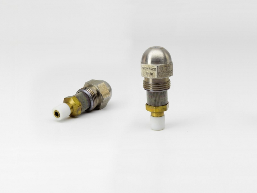
The BPS nozzles produce variable orifice flow rates by by-passing fluid from the nozzle swirl chamber. The orifice flow is regulated by controlling the by-pass line pressure.
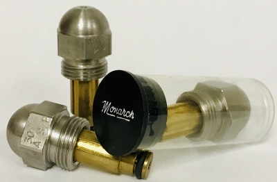
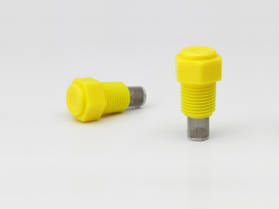
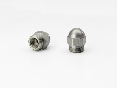
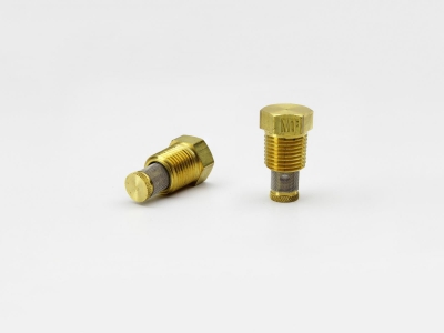
The nozzle tip and disc are made of the same heat resisting, high chrome grade of stainless steel used in our simplex or regular domestic oil burner nozzles. The combination locknut-strainer support is made of brass with a Monel strainer screen and a Viton „O“ ring. Nozzle adaptors (bodies) and fittings are made of brass. Nozzles in all sizes are furnished only with strainers, 120 mesh Monel up to and including 13.50 GPH and 80 mesh on larger sizes.
The BPS nozzles are designed and tested for operation at 100 psi. on #2 fuel oil, with the capacity and spray angle stamped on the nozzles at these conditions. Both the capacity and spray angle rating are based on having the by-pass line closed. Spray angle widens 5°-10° with the by-pass wide open.
The chart shows the orifice flow rates at specific by-pass line pressures and also the maximum pressure in the by-pass line when the by-pass is closed.
The BPS nozzles can be supplied with spray angles as follows: 30° in capacities from 3.00 GPH up to and including 30.00 GPH; 45° in capacities from .75 GPH up to and including 35.00 GPH; 60° in all listed capacities, 80° in capacities from 1.50 GPH up to and including 35.00 GPH, and 90° from 10.50 GPH up to and including 24.00 GPH.
It is possible to operate standard BPS nozzles up to 250 psi. line pressure, and at this pressure they will handle up to 70 S.S.U. operating viscosity oil. The BPS nozzles can be specially tested for operation at line pressures of 300 psi or more at additional cost.
BY-PASS PRESSURES vs. ORIFICE FLOWS
Shown is a pressure-flow chart for the 6.00 GPH BPS nozzle operating at 100 psi. oi line pressure on #2 fuel oil. The total fow through the nozzle orifice and the by-pass line when the by-pass is completely open is considerably more than the rated capacity of the nozzle, per last column of chart above. For capacity sizes larger than those indicated as available, we refer you to the E-180-H.
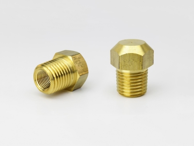
BY-PASSING NOZZLE ADAPTORS
The H-730-C by-passing nozzle adaptors are 2 1/16‘‘ long, made of 3/4‘‘ hexagon brass and are furnished with either 1/8‘‘ or 1/4‘‘ female N.P..T. oil inlet connections. They are equipped with a brass fitting on the side to accommodate 1/4‘‘ O.D. tubing for the by-pass line, and the distance between centers of the feed line and the by-pass line is 11/16‘‘. A dual by-passing adaptor, H-711, is also available to take two (2) BPS nozzles. Due to the necessity of combining inlet and by-passing flows of the two nozzles, the single inlet of the H-711 is 1/8‘‘ female N.P..T. located on the side of the adaptor and the single by-pass is 1/4‘‘ female N.P..T. located at the rear of the adaptor. The H-711 is made from 3/4‘‘ x 1 3/4‘‘ rectangular brass stock and is 2 1/8‘‘ long.